Jefferson Lab's Workbench Projects
Point to Point Wiring Guide
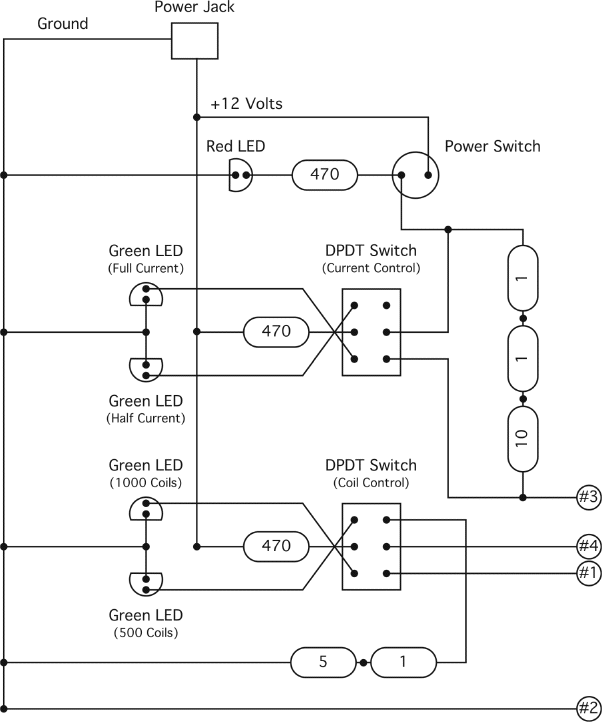
This diagram is a representation of the components as seen from inside the base. Resistors are represented by rounded rectangles. The flat end of the LED is the cathode. Note the orientation of the 1N4001 diodes. The numbered circles (#1, #2, #3 and #4) are the labeled leads from the electromagnet. Small, dark circles indicate a soldered connection.

Citation and linking information
For questions about this page, please contact Education Web Administrator.
