Jefferson Lab's Workbench Projects
Assembly
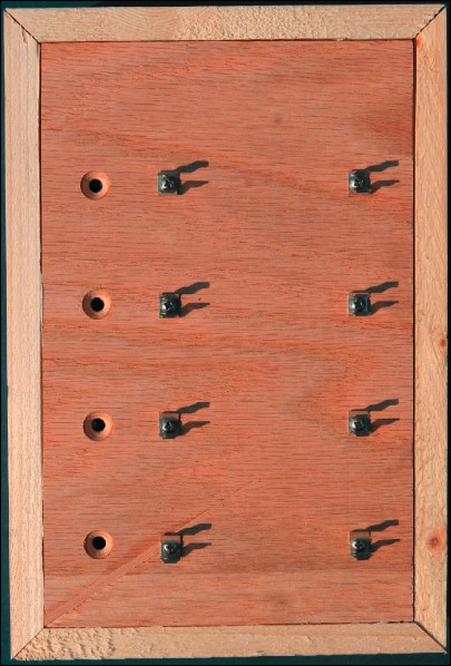
- Attach the 8 fuse clips to the top of the base using the 4-40 × 3/4" machine screws, 4-40 hex nuts and #4 washers. Align the fuse clips so that the test materials can be clipped between them.

The fuse clips have been attached to the top of the base.
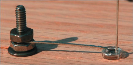
- Flipping the base over so that you can access its interior, insert the LEDs into their holes. If the leads of the LEDs are long enough, you can save yourself a bit of wiring by rotating the LEDs so that their cathodes are closest to their respective 4-40 × 3/4" machine screw. With luck, you will be able to bend the cathodes over and make contact with the 4-40 × 3/4" machine screw. You can then secure the cathode to the 4-40 × 3/4" machine screw by using another 4-40 hex nut to make a kind of cathode sandwich. If this method is used, make certain the cathode makes contact with the 4-40 × 3/4" machine screw at the 6 o'clock position. That way, tightening the upper 4-40 hex nut will tend to draw the cathode in.

Trapping the cathode between a pair of hex nuts can save some soldering!
- Insert the panel mount banana jack into the hole that was created in one of the 5 7/8" long pieces. The jack portion of the piece should be on the base's outer surface and the electrical hook-up portion should be in the base's interior.
- Use the Point to Point Wiring Guide, found in Appendix B, or the Circuit Diagram, found in Appendix C, to complete the wiring. Again, if the leads of the LEDs are long enough, you may be able to bend the anodes of neighboring LEDs together and solder them together directly.
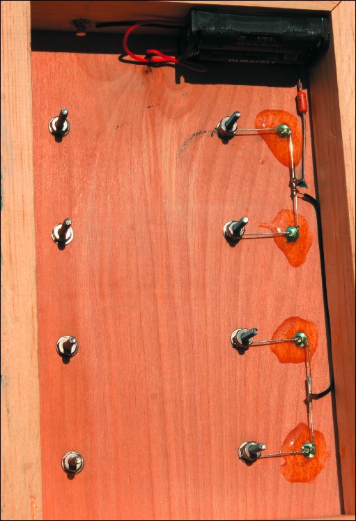
- Once the wiring is complete, secure the battery pack and the LEDs to the base with dabs of epoxy.

All wiring is complete and the LEDs and battery pack are secured to the base with epoxy.
- Insert two AAA batteries into the battery holder.
- Attach four adhesive feet to the bottom of the base and flip the contraption over. It's now more or less ready to go!
Citation and linking information
For questions about this page, please contact Education Web Administrator.
