Jefferson Lab's Workbench Projects
Final Assembly
- Attach the 6 ceramic spacers to the acrylic sheet. Use a #6-32 &tiimes; 1/2" machine screw and a #6 nylon washer to attach each ceramic spacer to the acrylic base. Do not over tighten the screws as the acrylic could crack.
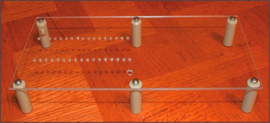
Six ceramic spacers have been attached to the acrylic base.
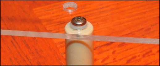
Close-up detail of one of the attached acrylic spacers.
- Attach the two banana plug panel mounts to the acrylic base. Again, be careful not to over tighten these items.
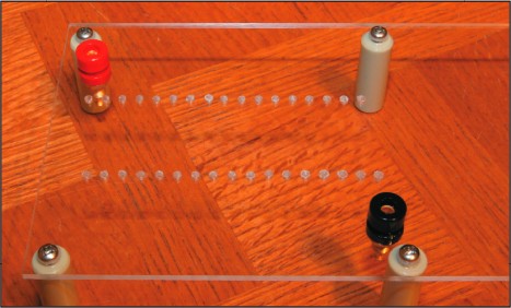
Two banana plug panel mounts have been attached to the acrylic base.
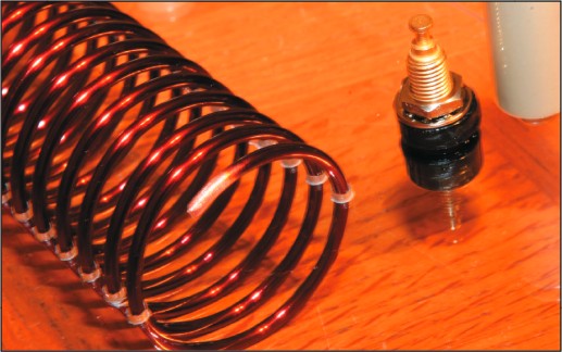
- Pull one end of the wire coil apart slightly. Use sand paper to remove about half an inch of the wire's insulating coating.
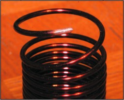
The insulation has been removed from a section of the coil.
- Feed the wire coil through the holes in the acrylic base. If the base is orientated as it is in the photographs above, the coil will pass upwards through the upper row of holes in the acrylic base and downwards through the lower row of holes.
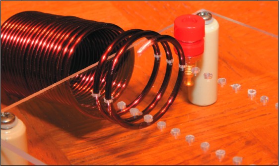
The coil is fed through the acrylic base.
- Keep feeding the coil through the acrylic base until it reaches the far banana plug panel mount.
Enough of the coil has been fed through the acrylic base so that it can be bent to reach the banana plug panel mount's solder post.
- Bend the leading end of the coil's wire so that it reaches the soldering post of the nearest banana plug panel mount. Solder the wire to the soldering post.
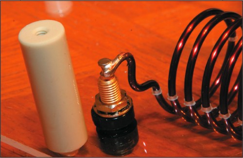
The coil's leading end has been soldered to the banana plug panel mount's soldering post.
- Bend the trailing end of the coil's wire so that it reaches the soldering post of the nearest banana plug panel mount. Trim the wire as necessary and remove about half an inch of the wire's insulating coating. Solder the wire to the soldering post.
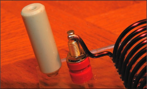
The coil's trailing end has been soldered to the banana plug panel mount's soldering post.
- That's it! Your magnetic field viewer is now ready for operation!
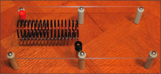
A completed magnetic field viewer.
Citation and linking information
For questions about this page, please contact Education Web Administrator.