Jefferson Lab's Workbench Projects
Assembly
- Place the bolt through the hole in the top rail of the magnet support frame. The coil at the end of the bolt should be pointed towards the base.
- Secure the bolt to the magnet support frame using a hex nut.
- Cut four lengths of hook-up wire long enough to run from the bolt secured to the top of the magnet support frame, along the top rail, down a side rail and through the 1/4" hole drilled into the side of the base with about 6" or so to spare.
- Solder one hook-up wire to each of the magnet's four leads. Cover each of the joints with heat shrink. Move the labels that are attached to the magnet wire to the ends of the hook-up wire, being careful not to confuse them.
- Carefully wrap and secure any loose magnet wire to the magnet support frame with clear packing tape. The idea is to prevent the magnet wire from moving or flexing in order to prevent breakage.
- Draw the four hook-up wires along the back of the magnet support frame from the electromagnet to the hole drilled in the side of the base. Secure the hook-up wires to the back of the magnet support frame with clear packing tape or staples. If a staple gun is used, make certain that the staples do not break through the hook-up wire's insulation.
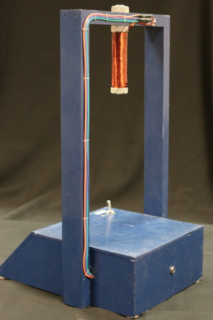
The magnet's hook-up wires are secured to the back of the support frame.
- Draw the four hook-up wires through the 1/4" hole drilled into the side of the base.
- Place and secure the momentary contact switch, the two DPDT toggle switches and the 2.1 mm power jack in their respective holes. Depending on the exact hardware used, it may be easier to remove an item from its mounting hole for wiring.
- Create a 2.5 ohm resistor by wiring two 1 ohm resistors and one .5 ohm resistor together in series.
- Create a 1.3 ohm resistor by wiring a 1 ohm resistor and a 1 ohm resistor together in series.
- Flip the base over so that you can access its interior.
- Place the red LED and the green LEDs in their respective mounting holes. Consult the Point to Point Wiring Guide or the Circuit Diagram in order to orient them correctly for wiring.
- Use epoxy to secure the LED's to the base by covering them with a small puddle. Do not cover the LED's leads with epoxy as you still need to solder wires to them. Once the LEDs are epoxied to the base, they will be nearly impossible to remove. If you are uncertain about your wiring skills, you may wish to epoxy these components after they are wired and are operating correctly.
- Find a convenient place within the base to mount the 2.5 and 1.3 ohm resistors. Secure them to the base with epoxy.
- Wire the components together. Use the Point to Point Wiring Guide or the Circuit Diagram, located at the end of this document, to guide you. Whenever possible, cover exposed joints with heat shrink.
- Once you have double checked your connections and you have finished soldering the joints, attach the four adhesive felt feet to the bottom of the base.
- Set the device upright and attach the adhesive lables to mark the switch settings. The momentary contact switch on the base's top platform is the magent's ON-OFF switch and should be labeled 'POWER.' The top two green LEDs indicate the power settings. The top LED in this group should be labeled 'FULL CURRENT' and the one below it should be labeled 'HALF CURRENT.' The lower two green LEDs indicate the number of coils used. The top LED in this group should be labeled 'ALL COILS' and the one below it should be labeled 'HALF COILS.'
- Give yourself a little pat on the back because you are done!
Citation and linking information
For questions about this page, please contact Steve Gagnon.