Jefferson Lab's Workbench Projects
Base Construction
- Cut an 8" long piece from the 1 × 4 white pine board. Miter cut both ends to a 45° angle. This piece will form the back of the base.
- Drill a hole in the back board to accept the 2.1 mm power jack. Since our power jack was not designed to be used with a material as thick as the pine board, a Forstner bit was used to remove the excess wood.
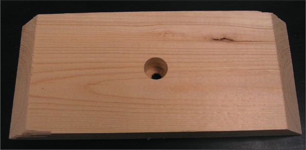
The base's back board had been cut and a hole for the power jack has been drilled through it.
- Cut two pieces from the 1 × 4 white pine board. Make each piece 11 7/16" long. These pieces will form the right and left sides of the base.
- Make a 45° angle cut along the face of the right and left side boards. When completed, the 'top' of these pieces will be 8" long and the 'bottom' will be 11 7/16" long. The angled faces of these pieces will eventually support the device's control panel.
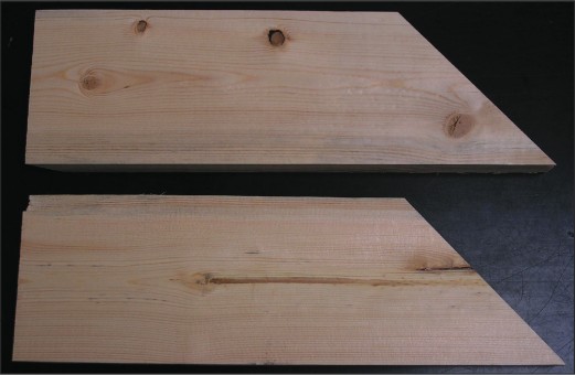
The right and left sections of the base.
- Miter cut the rear, interior edges of the right and left side boards to a 45° angel. Remember, these two pieces are not interchangeable. The miter cuts must be made on the correct edges.
- Join the right, left and back sections of the base to form a 3-sided, U-shaped box. Use wood glue and finishing nails to secure the joints.
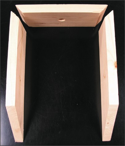
The three sections of the base, prior to joining, showing the correct miter cuts.
- Cut an 8" &imes; 8" panel from the 1/4" plywood. This panel will form the top of the base.
- Choose one edge of the top panel as the front and bevel it to a 45° angel. The dimensions of the base of the top panel should still be 8" × 8" after the bevel cut is made. It may be easier to make the top panel slightly larger than necessary and then trim it to the correct size as the bevel cut is made.
- Drill a hole in the top panel, near the front edge, to accept the momentary contact switch. Drill a second hole nearby to accept the red LED.
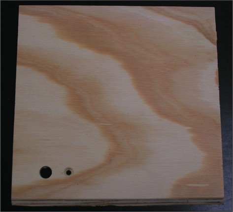
The top of the base has been cut and the front edge has been beveled to a 45° angel. Holes have been drilled for the momentary contact switch (large) and red LED (small).
- Cut an 8" × 5 9/16" panel from the 1/4" plywood. This panel will form the front of the base.
- Bevel the top and bottom edges of the front panel to a 45° angel. When complete, the front panel's profile will be a parallelogram. The top edge will be parallel to the top of the base and the bottom edge will be parallel with the bottom of the base. As with the top panel, it may be easier to cut this piece slightly larger than needed and then trim it to the correct size as the bevel cuts are made.
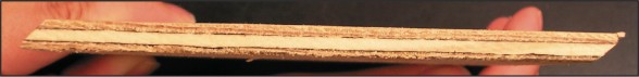
An edge-on view of the front panel showing the two 45° bevel cuts. The 'top' of the piece is to the left.
- Drill holes in the front panel to accept the two DPDT toggle switches and the four green LED's. The LED's will be used to indicate the position of the switches, so they should be clustered together.
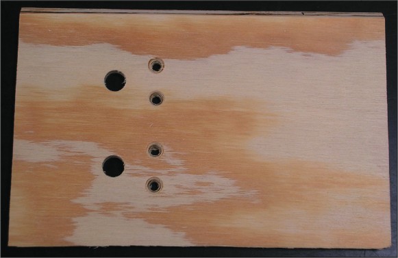
The front panel has been cut and the top and bottom edges have been given a 45° bevel. Holes have been drilled for the toggle switches (large) and green LEDs (small).
- Attach the top panel and front panel to the base. The front panel should be positioned so that it covers the front edge of the top panel. Use wood glue and finishing nails to secure these pieces to the base.
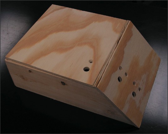
The lower base is assembled.
Citation and linking information
For questions about this page, please contact Steve Gagnon.